CNC machining remains one of the most practical bridges between digital design and functional product testing. It removes material directly from aluminum, steel, plastics, or engineering composites. The result is a durable prototype with realistic tolerances, surface finishes, and assembly behavior. That matters when a glossy 3D-printed model hides real manufacturing problems.
The central question is: How to integrate CNC machining into rapid prototyping workflows? A strong workflow connects CAD preparation, material selection, toolpath planning, machining, inspection, and design feedback. Each stage should reduce uncertainty. For example, a machined aluminum housing can reveal thread damage, heat buildup, or misaligned mounting holes before production tooling begins. It can also expose weaknesses in the design.
Todd Grimm, a respected manufacturing consultant and author, offers a useful perspective: “The best prototype is the one that teaches you something.” This idea supports the five methods explored in this article. CNC machining can accelerate functional testing, improve material validation, support low-volume production, reduce tooling risk, and strengthen design communication.
Small details matter. A 0.2-millimeter tolerance change may affect an entire assembly. A poorly selected cutter can leave visible marks inside a sealing surface. These lessons are easy to miss.
CNC is not always the fastest choice. Complex internal channels may require another process. Machining can also create unnecessary waste when designs are not prepared carefully. Still, with realistic expectations and disciplined inspection, it offers dependable evidence. The following approaches show how teams can use CNC machining more intelligently during rapid prototyping.
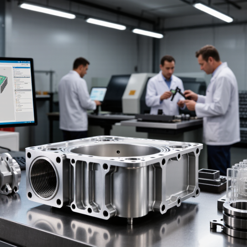
CNC machining makes form and fit testing tangible. A prototype can match the planned material, surface, and assembly conditions. This matters when a housing must slide over a seal or align with four fastener holes. In shop-floor practice, machinists often check the first part with calipers, gauges, and a coordinate measuring machine. Small errors become visible quickly.
Fit is rarely perfect at the first attempt.
The 2024 Wohlers Report valued global additive manufacturing revenues at about $20.8 billion in 2023. That growth shows rapid prototyping is expanding, but CNC machining still offers a useful reality check for functional parts. Unlike many printed samples, a machined prototype can reveal cutting-edge access, wall rigidity, thread engagement, and surface friction. These details often change the design.
Tolerance decisions need discipline. ISO 286-1 provides a structured system for limits and fits, yet designers sometimes assign tight tolerances without checking process capability. That choice can increase machining time and cost. A better workflow machines one representative part, records actual measurements, and compares them with the drawing. NIST guidance on dimensional measurement also stresses uncertainty, which should not be ignored during validation. I would not treat one successful assembly as proof of production readiness. Temperature, tool wear, and operator setup can still alter the result.
CNC machining turns a prototype into a testable part, not merely a convincing shape. A machined aluminum bracket can reveal whether bolt holes align, edges crack under load, or vibration loosens fasteners. Use the intended material and production-like geometry where possible. Then test the prototype under defined loads, temperatures, and cycle counts. Record measurements before and after testing; a caliper reading alone may miss distortion around a loaded mounting hole. One limitation: a single successful test does not prove repeatable performance.
Industry research supports linking physical trials with measurable production data. Deloitte’s 2024 manufacturing outlook reported that 86% of surveyed manufacturing executives expected smart factory solutions to be a primary driver of competitiveness within five years. For prototype work, the practical lesson is modest: capture test conditions and results in a consistent digital record. Compare each machined revision against the same baseline, or changes in performance may reflect a different setup rather than a better design.
Tips: Add small witness marks near stress points, photograph cracks beside a scale, and note tool direction and machining setup. Test the weakest feature first. It may expose an overlooked failure mode. Keep one unmodified sample as a control, and resist treating a clean-looking surface as proof of strength.
Comparing typical tensile strength helps teams shortlist CNC-machined materials for functional prototype testing. Values are approximate representative figures; actual properties vary by grade, temper, and supplier.
CNC machining is useful when a prototype must match a finished part’s strength, fit, or surface. Material choice changes the result. Aluminum cuts quickly and keeps weight low, making it practical for housings and brackets. Steel handles higher loads but takes longer to machine. A small steel test piece can also reveal tool-access problems early. That matters.
Plastics offer different trade-offs. Acetal machines cleanly for sliding parts, while acrylic can show transparent shapes but may chip under stress. Nylon suits wear-prone components, though moisture can affect its dimensions. For a quick fit check, printed plastic may cost less than machined stock. But its layer lines and strength can mislead. The cheapest prototype is not always the most informative.
Compare CNC machining with additive manufacturing and sheet-metal fabrication before choosing a route. Printing supports complex internal shapes with little setup, while machining produces precise surfaces and dependable material properties. Sheet metal can be efficient for folded enclosures, but it is less suitable for solid, sculpted forms. Ask what the test needs to prove: appearance, assembly clearance, heat resistance, or load capacity. Then select the process around that question. Sometimes the first choice is wrong. A short trial cut can expose burrs, tool marks, or thin walls that looked harmless in CAD.
CNC machining turns a digital prototype into a precise, testable part. In rapid prototyping, its greatest value appears through repeated design cycles. Engineers can machine an enclosure, test its fit, and identify interference around screw holes or sliding surfaces. The next version may change within hours. This feedback is more useful than relying only on screen-based simulations.
A practical workflow begins with a functional prototype, not a perfect one. Measure critical areas with calipers, inspect surface marks, and record assembly problems. Then adjust wall thickness, clearances, or mounting features in the CAD model. Machining the revised part reveals whether the improvement works in real conditions. Sometimes, a tighter tolerance creates unnecessary cost. I have seen small cosmetic details distract teams from a weak hinge or poor access for tools. That mistake is easy to repeat.
Tips: Keep a revision log for every machined part. Mark changed features directly on inspection notes. Test the prototype under realistic loads, temperatures, and handling conditions. Avoid refining every detail too early. A simple aluminum or plastic block can expose major ergonomic problems before final materials are selected. Ask another engineer to inspect the part without seeing the design intent. Their questions often reveal unclear interfaces. Iteration should be controlled, but not rigid. One overlooked measurement can send the next prototype in the wrong direction.
| Method | Primary Prototyping Goal | Typical Materials | Typical Dimensional Tolerance | Typical Lead Time | How Iteration Improves the Design | Best Fit |
|---|---|---|---|---|---|---|
| Functional Fit Prototypes | Verify assembly, mating surfaces, clearances, and basic mechanical operation before production tooling. | Aluminum alloys, engineering plastics, stainless steel, and mild steel. | Approximately ±0.05–0.13 mm for commonly machined features, depending on geometry, material, and process control. | About 3–10 business days for simple to moderately complex parts. | Each machining cycle exposes interference, excessive clearance, alignment errors, or difficult-to-assemble features that can be corrected in the CAD model. | Housings, brackets, fixtures, covers, mating components, and mechanical assemblies. |
| Design-for-Manufacturing Validation | Identify features that may increase machining time, tooling complexity, scrap risk, or production cost. | Aluminum, brass, plastics, carbon steel, stainless steel, and titanium for demanding applications. | Commonly ±0.05–0.25 mm, with tighter tolerances reserved for critical features and verified through inspection. | About 4–12 business days, depending on material availability and feature complexity. | Successive prototypes help simplify deep pockets, reduce unnecessary tight tolerances, improve tool access, and replace difficult setups with more manufacturable geometry. | Parts intended for CNC production, die casting, injection molding, or other downstream manufacturing processes. |
| Material and Surface-Finish Evaluation | Compare the behavior, appearance, weight, wear resistance, and corrosion performance of candidate materials and finishes. | Aluminum, stainless steel, brass, acetal, nylon, ABS-like plastics, and other machinable engineering materials. | Typically ±0.08–0.25 mm; surface roughness may range from approximately Ra 0.8–3.2 µm before optional finishing, depending on machining conditions. | About 3–15 business days, including optional anodizing, plating, bead blasting, or painting. | Testing several material or finish combinations reveals whether the prototype meets visual, tactile, thermal, wear, and environmental requirements before design freeze. | Consumer products, visible enclosures, handles, wear components, heat-management parts, and outdoor products. |
| Engineering Test Prototypes | Measure strength, stiffness, thermal response, vibration behavior, fatigue performance, or fluid-handling capability. | Structural aluminum, stainless steel, carbon steel, titanium, brass, and high-temperature engineering plastics. | Approximately ±0.05–0.20 mm for controlled features; test-critical dimensions should be specified and inspected individually. | About 5–20 business days, depending on material, inspection requirements, and post-machining treatment. | Test results from each version guide changes to wall thickness, rib layout, fastener locations, fillets, load paths, and tolerance allocation. | Automotive, aerospace, robotics, industrial equipment, laboratory devices, and load-bearing mechanisms. |
| Low-Volume Pilot Parts | Produce a small quantity of near-production parts for user trials, field testing, assembly training, or early market feedback. | Production-grade aluminum, stainless steel, brass, steel, and durable engineering plastics. | Often ±0.05–0.25 mm for general features, with tighter requirements applied only where function demands them. | Approximately 1–4 weeks for small batches, depending on quantity, inspection, finishing, and assembly needs. | Feedback from real users and assemblers helps refine ergonomics, serviceability, assembly sequence, packaging, and reliability before larger-scale production. | New product launches, replacement parts, specialized equipment, pilot programs, and products with uncertain demand. |
Typical values are indicative industry ranges. Actual tolerance, surface finish, cost, and lead time depend on part geometry, material, machine capability, inspection requirements, batch size, and post-processing.
CNC machining helps teams test real parts before committing to low-volume production. The first advantage is material accuracy. Engineers can machine prototypes from production-grade metals or plastics. This reveals stiffness, heat response, thread strength, and surface wear more clearly than printed models. A machined housing may expose a weak wall near a mounting hole. That detail can prevent an expensive tooling change later.
The second method is functional testing. Use CNC prototypes for assembly checks, load tests, and repeated operation. Measure critical dimensions with calibrated equipment. Record actual results, not expected values.
The third method is design refinement. Adjust tolerances, corner radii, wall thicknesses, and fastener access after observing the part in use. Small changes matter. However, not every prototype needs maximum precision. Excessive tolerances can increase cost without improving performance.
CNC machining also supports pilot batches for low-volume production. Produce a small quantity, then inspect consistency across every part. Check fit, finish, machining marks, and dimensional drift. This step builds reliable manufacturing data before larger commitments.
Finally, use prototype feedback to prepare clear drawings, inspection points, and process notes. Experienced teams often overlook documentation. That mistake returns later. A validated design should survive real handling, not only pass a computer model. Leave room for honest revision when test results challenge the original design.
It creates a testable part with realistic geometry and material properties. You can check fit, strength, and surface quality.
Check bolt-hole alignment, cracking, vibration, and distortion under load. A clean surface proves little.
Keep test conditions consistent. Record loads, temperatures, cycle counts, and measurements for every revision.
Note the machining setup and tool direction. Photograph cracks beside a scale, and add witness marks near stress points.
Aluminum is light and machines quickly. It can be a practical choice, though the design still needs load testing.
Steel handles higher loads but takes longer to machine. Nylon can wear well, yet moisture may change its dimensions.
It can help with quick fit checks. But layer lines and strength may mislead, so it may not suit load testing.
Match the process to the question: appearance, clearance, heat resistance, or load capacity. A short trial can reveal flaws.
No. One test cannot show repeatability. Keep a control sample, and test more than once.
CNC machining is a practical way to turn prototype designs into accurate, tangible parts for rapid evaluation. It helps teams assess a design’s form, fit, and assembly before committing to larger production runs. Machined prototypes can also be made from materials suited to real-world use, allowing engineers to test strength, durability, and performance rather than relying only on visual models. Comparing different materials and manufacturing options through prototypes can reveal trade-offs in cost, functionality, and production readiness.
A key advantage is the ability to refine designs through repeated machining. Teams can use test results to adjust dimensions, features, and material choices, then produce updated parts for further evaluation. How to integrate CNC machining into rapid prototyping workflows? Begin by identifying which design questions a prototype must answer, select materials that match the intended tests, and plan each iteration around specific improvements. Once the design has been validated, CNC machining can also help prepare parts for low-volume production, supporting a smoother transition from prototype to finished product.

Gemnexa CNC